Bourke 30 Explained In Simple Terms
Hot Rod Magazine, 1954
This is an era of new engines. We are quite sure this is true for we read all about the revolutionary new engine
designs in advertisements everywhere and listen intently as radio and TV personalities explain the remarkable
engineering advancements contained in our present day automobile engines. Much has been accomplished in
the past few years by beefing up the lower ends, converting to overhead valves, shortening the stroke to reduce
piston speed and converting to complex four-throat carburetors.
The basic design, however, has been unchanged for over 50 years. Even longer than that if we care to go way
back to the late 1800s or early 1900s when our successful racing engines of today were first put on paper.
Designers and engineers of that period knew how to lay out an efficient engine comparable with our best of today,
but alas, they were not blessed with the metallurgical advancements used freely in our present day engine
laboratories. Their designs were forced to remain on the drawing board until metals were produced that could
withstand the tremendous stresses and strains developed in high output four-stroke engines.
Perhaps we are now ready for the Bourke engine, or better yet, now that we have hopped up every Detroit engine
to the point of self-destruction, the Bourke engine is now ready for us. It may not be the last word in design, for all
designs will forever be improved upon, but at least it is a step in the right direction.
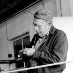
Russell Bourke, of Portland, Oregon, sole inventor and designer of this new engine, has long sought an answer
to the wasted energies and to the reduction of stresses and strains in the conventional engine. It all began back in
1918 when Bourke was teaching engine theory and maintenance in the Air Service School at Kelly Field, Texas. Endless
discussions with other instructors and students soon convinced Bourke that much was left to be desired in the internal
combustion engine using the Otto cycle. Heavy, inefficient and employing too many precision parts, they would one
day become as extinct as the stream-powered car.
For fourteen years Russell studied the problems and in 1932 came up with a new engine and his first working
model. This first engine was basically successful but there was room for many refinements. In 1938 Bourke built a f
our cylinder radial to be tested for outboard marine use. This engine literally put itself back on the shelf. It had too much
torque for existing drives. A less powerful two cylinder opposed unit was then built and it proved successful after 2000
hours of testing in a boat.
 All
the lost energies present in the four-stroke engine have been put to work. Like a Judo expert that makes use of his
adversary's strength and momentum. Bourke had made every lost motion in the engine perform a needed operation. All
the lost energies present in the four-stroke engine have been put to work. Like a Judo expert that makes use of his
adversary's strength and momentum. Bourke had made every lost motion in the engine perform a needed operation.
The engine and its functions are simplicity exemplified, yet the engineering and development involved are by
no means simple. It is of the opposed cylinder, two-stroke type. Russell calls it a "mono-stroke engine". Indeed it is
by it's construction and operation. Co-operative pistons are connected to one rigid connecting rod that shuttles through
an oil filled, crankcase sealed off from the cylinders hence, no oil changes needed.. There is no blow by introduced
into the crankcase to pollute he oil. There are only two moving parts in the engine: 1-The piston-connecting-rod- yoke
assembly; 2-The crankshaft. All other parts usually found in the conventional engine have been discarded.
There is no flywheel as the crankshaft is dynamically balanced for all speeds and is not connected solidly with the
piston rod assembly. Operated through a streamlined, high speed version of the
Scotch-Yoke, all kinetic and inertial
forces generated by the piston rod assembly are used directly for charging and compression. The forces delivered to
the crankshaft are then one-directional and permit a greater power output with almost instantaneous acceleration
under load.
Before we attempt to follow the pistons through a complete crank revolution, let us take a close look at the parts
involved.
CRANKSHAFT
 This
counter-balanced unit, below, supported at each end in double row ball bearings, has only one crankpin and on it is
mounted a three-in-one or triple slipper bearing. The inner split (hub) ring turns freely on the crankpin and serves as a
seat and speed reducer for the middle or intermediate ring. The outer ring serves as contact point with the rod assembly
and through it all energy generated by the pistons is transmitted to the crankshaft, free to ride up and down in the yoke
(center of the piston rod assembly) and so develops the rotational action of the crankshaft. The crank can be turned either
direction so that the engine can be run clockwise or counterclockwise at will. The direction of the rotation is governed by
the timing of the ignition system. This
counter-balanced unit, below, supported at each end in double row ball bearings, has only one crankpin and on it is
mounted a three-in-one or triple slipper bearing. The inner split (hub) ring turns freely on the crankpin and serves as a
seat and speed reducer for the middle or intermediate ring. The outer ring serves as contact point with the rod assembly
and through it all energy generated by the pistons is transmitted to the crankshaft, free to ride up and down in the yoke
(center of the piston rod assembly) and so develops the rotational action of the crankshaft. The crank can be turned either
direction so that the engine can be run clockwise or counterclockwise at will. The direction of the rotation is governed by
the timing of the ignition system.
PISTON-ROD-YOKE ASSEMBLY
 The
piston-rod assembly is made up of two machined plates that form the yoke, two rod extensions, two pistons with pins that
fix them into permanent position (they do not swivel or turn on the piston as in conventional engines), and two rings on
each piston. The two rod extensions are guided through pressure sealed bushings in the cylinder base of the crankcase. The
piston-rod assembly is made up of two machined plates that form the yoke, two rod extensions, two pistons with pins that
fix them into permanent position (they do not swivel or turn on the piston as in conventional engines), and two rings on
each piston. The two rod extensions are guided through pressure sealed bushings in the cylinder base of the crankcase.
The piston-rod-yoke assembly is one of the two moving parts of the Bourke engine. The three-in-one bearing on the
crankpin, above, slides up and down in the machined yoke. The slot in the side of the piston allows the new air/fuel
charge to begin its escape into the transfer jacket, thus allowing a smoother flow, without pulsation.
CRANKCASE
The crankcase is a precision machined aluminum casting with two face- plates (in which the crank bearings are
contained) that is completely sealed off from the cylinders when the engine is buttoned up. No gaskets are needed or
used, only o-rings.. No oil filter is needed and Bourke claims that the crankcase oil is good for the life of the engine. The
level must be kept up, however, to compensate for any possible leakage and ring usage. As the case is sealed off from
the cylinders, and consequently the products of combustion, the oil is free of contamination. Being devoid of any potential
lubrication failures, the engine can be run up to top rpm under full load on a cold start. One test engine has run over 1100
hours at between 1,000 and 10,000 rpm with no sign of wear on either of the moving parts and the oil looks as good as
new.
CYLINDERS
Cast of Alcoa 365 heat treated aluminum alloy, as are all the other aluminum castings, the two cylinder block contains
many odd features. At first glance, the inside walls of the cylinders appear to be full of holes. These are the ports for intake
and exhaust and their arrangement is one of the reasons why the engine is so successful. They replace, in effect, the
operation of valves, cams and all the other breathing mechanisms upon which the conventional four stroke engine is so
dependent.
LUBRICATION SYSTEM
 Both
parts in the crankcase are bathed in oil. Oil is supplied between the two rings at the bottom of the stroke from a small hole
in the cylinder wall. Oil reaches this opening via matching rifle drilled holes in both the cylinder block and the upper part of
the crankcase. Pressure to drive the oil through this passage is in reality the centrifugal force of the oil as it leaves the
whirling crankshaft and flies into the opening. As long as pistons and rings are well supplied with oil, no more oil feeds,
but as oil is lost from the rings it is replaced by fresh oil, making lubrication automatic, economical and dependable. Both
parts in the crankcase are bathed in oil. Oil is supplied between the two rings at the bottom of the stroke from a small hole
in the cylinder wall. Oil reaches this opening via matching rifle drilled holes in both the cylinder block and the upper part of
the crankcase. Pressure to drive the oil through this passage is in reality the centrifugal force of the oil as it leaves the
whirling crankshaft and flies into the opening. As long as pistons and rings are well supplied with oil, no more oil feeds,
but as oil is lost from the rings it is replaced by fresh oil, making lubrication automatic, economical and dependable.
The Bourke Cycle
Now let's follow the piston-rod assembly through one crank revolution:
As the crank bearing rolls across the connecting rod shoe in the yoke assembly, the piston dwells at the top of its
stroke for a measurable amount of crank travel, approximately 45 degrees, holding the burning gases until they are
completely consumed, no further flame, and the maximum pressure has developed.
Just prior to that as the piston traveled upward toward tdc, the intake ports were opened by the piston skirt and the
area between the piston and crankcase facing (approximately 30 cubic inches) had filled with an air / fuel mixture under
a vacuum created by the pistons upward travel.
Pressure is generated at the top of the piston forcing it inward as soon as the crankpin reaches a point of mechanical
advantage.
Moving inward, the piston transmits all energy to the crankshaft through the yoke assembly and the skirt closes the
intake port and bottom transfer port so that the air / fuel mixture underneath the piston is compressed against the
crankcase facing surface. The piston skirt drops deep into a recess that is machined into the crankcase facing, thus
allowing compression of the air / fuel charge to a pressure of approximately 50 psi.
As the piston dwells at the end of its inward travel (for another 45 degrees of crankshaft rotation), a port in the piston
skirt is alighted with a port in the cylinder wall. The air / fuel mixture (now under pressure), is allowed to escape into the
transfer jacket outside the cylinder wall and enter the cylinder again through the port above the piston via the same
transfer jacket. A turbulating fin and the surface design angle on the piston join in directing the air / fuel mixture in a
swirling motion to the top of the cylinder.
As the pressure charge continues it's expansion, it moves down into the cylinder and forces the spent gasses through
the now open exhaust port that is above the intake port on the same side of the cylinder wall.
At this time, the opposite piston is receiving it's power impulse and is ready to start inward, closing the transfer and
exhaust ports on opposite sides of each other and compressing its fresh air / fuel charge as it moves upward.
The upward motion of the same piston also creates a vacuum beneath the piston to draw in the new air / fuel mixture
(only air if injectors are being used), for it's next cycle as its skirt uncovers the intake port.
At about 90 degrees before top dead center, ignition occurs as compression continues.
As compression continues and pressure increases, the air / fuel mixture burns more rapidly and a force or cushion is
built up sufficient to stop the movement of the mass (pistons and rod assembly) and as the crankshaft throw moves across
top dead center, the burning charge is completely consumed and the pressure is released to send the piston back inward,
so ending the second 180 degrees of crankshaft travel.
Since the same action takes place at each end of the mass (piston-rod-yoke assembly) and since the forces generated
are equal, the moving mass can be likened to a tennis ball being batted back and forth by players of equal strength. As
the mass is not tied solidly to the crankshaft, it simply imparts its energy to it in passing. Therefore no energy is absorbed
from the crankshaft to complete the cycle.
Combustion / Oxidation Process
Low grade fuel has proven to be the most satisfactory in the Bourke engine. Its low burning characteristics build
a cushion and its high heat potential is released at high compression, while the piston is dwells at top dead center
and all of the air / fuel mixture is consumed (oxidized).
Since all heat is extracted at the top of the piston travel, temperatures over 2000 degrees F and pressure over
1000 psi are generated, the flame dies out completely, and the rapid expansion of the gases on the inward stroke cool
themselves and create, in fact, a refrigeration cycle. Paper matches held in the exhaust port will not light and the gases
at the port feel only warm to the touch when all adjustments are correct. Best results to date have been achieved with a
mixture of three parts white gas (Coleman stove oil) to one part brown gas (1-K Kerosene) but can be varied to suit local
fuels, altitude, etc.
From the foregoing, it is obvious that this cannot be thought of wholly as a conventional reciprocating engine. The
power curve is similar to that of a turbine engine. (See graph below) It has, however, the advantage of extreme economy
which is not possible with a turbine engine. Engine speeds approaching those of turbines will be possible when a faster
firing ignition system can be devised.
In summing up the operation of this all new engine, we discover quite a number of outstanding features:
- A reduction of moving parts to complete 4 cycles.
- No dead strokes to absorb power.
- Reduction of weight, complexity and parasitic losses due to lack of flywheel, camshaft, cam gears, poppet valves, etc.
- A far greater power output for any given displacement as the engine can be operated at much higher rpm's without
appreciable power fall-off. Naturally valve float is non-existent in an engine that has no valves.
- There is absence of both sharing stresses and cylinder wear as the pistons operate in a straight line and never
come into contact with the cylinder walls. Rings serving as a compression seal only, are made of low tension material
and create only a minimum of friction and wear on the cylinder walls.
- The engine has no mechanical sounds, can be operated in any position desired, can be run clockwise or
counterclockwise at will, all parts are interchangeable, and there is no need of specialized tools or machinery to
manufacture it.
- It operates on very low octane fuel with practically no exhaust fumes, no flame and very little waste heat.
These facts are all very interesting but the thing that will be of primary interest to hot rodders and piston heads
everywhere is the fact that these 30 cubic inch, two cylinder opposed engines can be bolted together in clusters to achieve
an engine of almost any displacement desired! The total weight of each 30 cubic inch engine is only 38 pounds.
The next question on every ones lips is, "how many horses will it deliver?"
The final answer to this question is an unknown factor. The horsepower is limited only by the number of cylinders
and rpm's the engine can turn. So, use your imagination and of course the information contained in this article. Do the
math. It's quite impressive in any case and far superior to any conventional 2 or 4 stroke or Wankel engine. Bourke's own
specially built battery ignition system will turn up to 15,000 rpm, or an estimated 114 brake horsepower. Experiments
have been made using flow plugs and with them the engine is reported to have turned well in excess of 20,000 rpm!
Glow plugs, however, will hardly be acceptable in closed competition for the engine cannot be shut off at will. There
are possibilities of adapting an efficient fuel valve, built into the engine near the injector nozzles, that could shut the engine
down in short time. Perhaps a compression release, similar to diesel installations would work even better.
Continued on page 52 of the July issue of Hot Rod Magazine 1954, minus the changes made by the
editor of this article.
An electronic copy of the original Bourke Engine
Documentary, by Lois Bourke, may be purchased through
Bourke-Engine.Com. The documentary contains more
information, pictures, theories and basis for Russell Bourke's designs and discoveries regarding his remarkable
engine! |